Do you remember when you were young and you pulled out the map to help your parents plan the family vacation? There was a scale on the map giving you the amount of miles per inch so we took a piece of string and ran it along with our route on the map to determine the distance based on the length of the string. While this system works for maps there is a different system in use for the drawings used by automotive engineers when designing a new vehicle or vehicle component. This very specific language ensures that no matter who receives a drawing that they will be able to read and understand the drawing and all associated parameters. Geometrical Dimensioning and Tolerancing (GD&T) is a system established to commonize the drawing which is considered the ‘bible’ for all geometric tolerancing practices and requirements.
Building a vehicle is like assembling a giant three-dimensional puzzle and without a common language between manufacturers the chances that the parts fitting together is slim. GD&T is a system of symbols used in engineering drawings that specify the shape, orientation, size, and critical features of the object of the drawing. This system allows everyone from the designer to the production manager to speak the same language when it comes to the drawing. GD&T specifies helps to control all geometry and dimensions and make them readable by a co-worker, customer or supplier.
What is GD&T and when is it used?
 The American Society for Mechanical Engineers (ASME) has developed the standards that govern all geometric dimensioning and tolerancing that are used in the automotive industry on all engineering documents and drawings. ASME Y14.5-2009 is the most recent version of this specification.
One of the most important roles of design engineers is to explain all the critical dimension and tolerances so that anyone who reads the prints is able to understand the drawings and build it to the required specifications. Without this type of system, each subcomponent would be at the whim of the manufacturer and it would be highly unlikely that the pieces would fit together.
The automotive industry has many critical areas where GD&T is utilized the first and foremost being any time that components and features must be interchangeable. Component manufacturers produce in bulk and when the final assembly manufacturing engineer selects one component from the bulk shipment to assemble onto a vehicle they must be assured that it has been assembled to the same dimensions and specifications as the remaining parts in the shipment. It should always fit in the correct location within the vehicle without interference and will function exactly as specified. If a component does not fit within the required parameters some manufacturers will attempt to rework the part but a majority will just scrap the part causing unnecessary cost in the manufacturing process. Process engineering also relies on GD&T to ensure that all automated equipment and supporting tooling are interchangeable and that spares are available in the case of repairs.
GD&T basics overview
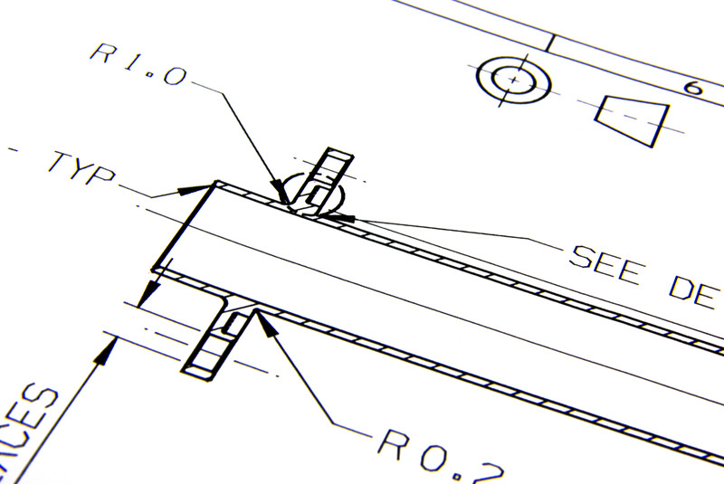
Whether you learn the GD&T symbols in school or on the job, you should make sure you have a good understanding of them in automotive engineering. The ASME Y14.5 has basic standards that define key geometric characteristics for the following key characteristics: straightness, flatness, roundness, cylindricity, profile, parallelism, perpendicularity, angularity, concentricity, runout and true position. Each of these key parameters has a symbol that represents each characteristics.
Here is a great website on GD&T Symbols that I use at work all the time. It is a fairly new website but contains the best content by far.
For more information on GD&T Training Options – be sure to check out the GD&T courses available at GD&T Basics.
The first group of symbols define the form of the component include straightness, flatness, circularity and cylindricity:
- Straightness: The requirement where the surface of the part or component must fall within specified tolerances and be flat or not bend outside a specified area.
- Flatness: The degree to which the surface of the component or part approximates a mathematical plane. No point along the surface can exceed the tolerance plane that is given.
- Circularity: Describes how closely the object approaches the perfect shape of a circle and indicates the lack of any edges or corners on the part.
- Cylindricity: Describes how well a part adheres to a perfect cylinder. The tolerance is the 3D version of circularity.
The next group focuses on the orientation of a surface or an axis:
- Perpendicularity: Indicates how closely the connection between two parts approaches a 90° or right angle. Can be used on surfaces that mate together or on an axis.
- Angularity: Controls the surfaces of two features at a specific angle. This is not the same as an angle tolerance like 30° ± 5°.
- Parallelism: Defines a key parameter where two lines within a design will not ever meet. Parallelism is commonly used to make sure two surfaces, like the top and bottom of a part, are parallel to each other.
Location, runout and profile are the last group and they specify where in space a surface, axis or point is located:
- Concentricity: Also known as coaxiality, concentricity is a tolerance that controls one parts central axis to another part.
- Symmetry: Defines the relationship between different measurement surfaces within a part over a centered datum plane.
- True Position: One of the most versatile symbols in GD&T, True position allows control over the exact location of a point, axis or feature..
- Runout and Total Runout: Specifies the amount of inaccuracy allowed in a rotating mechanical system. Basically runout is measured by rotating a part, (keeping a fixed plane to the datum that is given in the symbol) and measuring how mush variance is in the part using a gauge. The part cannot go above or below a given limit.
- Profile a Line or Profile of a Surface: The catch-all symbol for surfaces profile tolerances can control the size, location, orientation or form of any surface feature. Usually these symbols are used with advanced surfaces like the hood of a car.
One of the most important concepts beyond just the symbols is the use of datums. Datums are references on an engineering drawing that all other features are referenced from. All of the symbols, besides the first group listed, can rely on datums to help define the part.
GD&T in automotive engineering
All of these symbols and more are available for engineers and designers to describe all the key parameters for components, parts and equipment that are used in the production and design of an automobile. Consider the following example from an automotive application for a small shaft made on a lathe:
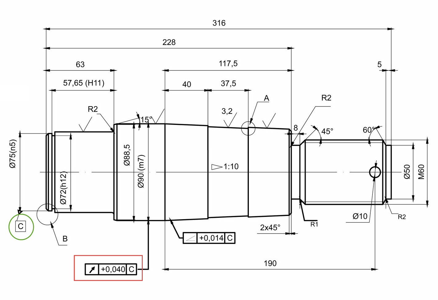
As you can see from the drawing using the specifications and the symbols that GD&T provide you can clearly specify that the outer most diameter (90 m7) needs to have a runout less than 0.040 mm (red box) to surface C (green circle). This means that if you held the part at location C and rotated it, and placed a needle gauge on the part to detect how much that OD fluctuates, it should not detect more than 0.040 mm. This prevents wobbling of a part.
All engineering industries benefit from using GD&T to more clearly define their drawings and eliminate the limitations with a basic coordinate based system. As an automotive engineer, designing with GD&T is an industry standard to clearly describe how a unit is to be manufactured so that it fits within the top level assembly. If you want to become an automotive engineer, GD&T is a must for you to learn. By using this common language engineers and designers can specify the key parameters of each component and ensure that it will fit within the parameters and reduce scrap when the vehicle goes to production.
Comments 4
This material is very important for my knowledge about th theme. Thank You.
Hello
In this drawings dimensions dis 75(n5) , dia 72(h12) , dia 90(m7) . This n5 , h12 ,m7 are what defines..
Limits and fits: ISO 286-1 and/or ANSI B4.2
Thanks bro for sharing with your experience, it is really helpful for guys like me.